

CT series Round FRP Cooling tower

1, CT type round FRP Cooling tower application range
The CT circular FRP cooling tower adopts galvanized steel frame, and the shell adopts FRP material. Internal as required with ordinary PVC heat transfer filler, or high-temperature pp heat transfer filler. Because the structure is simple, the cooling effect is good, and the price is cheap, widely used in the injection molding machine cooling, air compressor cooling, intermediate frequency electric furnace cooling and other water quality requirements are not high cooling equipment.
2, CT circular FRP cooling tower and DBNL type round FRP Cooling tower Difference
CT circular FRP Cooling tower and DBNL type round FRP Cooling tower, the user in the selection of the time must pay attention. CT cooling tower using cold tons as the basic unit, such as CT-80 model cooling tower, indicating that the refrigeration capacity of 80 cold tons, after the unit conversion can be calculated, the actual amount of water treated is equivalent to 62.4m3/h. The DBNL cooling tower is different, DBNL uses water tons as the basic unit. DBNL-80 means that the amount of water treated is 80m3/h. That is to say, DBNL-80 is much bigger than CT-80. This is due to historical reasons.
The bottom inlet of the CT cooling tower adopts the net Inlet Air window, which is easy to disassemble, but the disadvantage is easy to break. and DBNL type cooling into the wind window using FRP blinds. The use of fiberglass blinds not only beautiful shape, but also long service life, not easy to break and other advantages. But the downside is that the cost is higher. Therefore, the same level of cooling tower, CT type is much cheaper than the DBNL type.
3. Principle of CT circular FRP Cooling tower

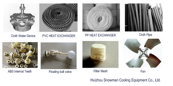
① motor, ② fan, ③ filler, ④ inlet and outlet and recharge port, ⑤ catchment tray, ⑥ into wind window, ⑦ cloth pipe, ⑧ shell
As can be seen from the schematic, the cooling tower enters the cooling tower from the bottom of the tower and, under the pressure of the pump, passes through the middle column to the top of the cooling tower. The top of the middle pipe can rotate the cloth water to turn the head, the cooling tower through the head into the various branch tubes. The tube is drilled with a series of small holes, and the cooling water is sprayed out through these small holes and sprinkled onto the filler. Because the cooling water through the small hole ejected in the direction of the filler vertical direction has a certain angle, so the spray out of the water will give the cloth pipe a moment. This moment pushes the cloth water and turns its head constantly spinning. The cooling water passes through the filler and travels evenly on the surface of the PVC filler. The heat of the water and the cold air in the gap between the filler heat exchange, the water is cooled and dripped into the bottom of the catchment disk, and hot air will be the top of the wind machine into the atmosphere, new dry cold air from the inlet window into the supplement. The cooling water dripping into the catchment tray is sucked away by the pump and re-enters the cooling cycle.
It is often asked how many degrees can the cooling tower cool the water? In fact, from the principle of cooling tower, it is very simple. Hot water in the filler with the air heat exchange, the maximum heat exchange is the temperature of the water and the temperature of the air is equal, the heat exchange will stop. Thus, the temperature of the cooling water is consistent with the ambient temperature. But there is one thing that cannot be ignored, that is, the evaporation of water, water evaporation needs to absorb heat, water evaporation will lead to lower water temperature. The drier the air, the more intense the evaporation, the lower the outlet temperature of the cooling tower. Therefore, the effluent temperature of cooling water is determined by two aspects: Heat transfer and evaporation. These two aspects determine that the cooling water temperature will be lower than the ambient temperature, higher than the wet bulb temperature.
4, CT type of circular FRP cooling tower composition
5, CT type of circular FRP cooling tower technical parameters


| Model | CT | 10 | 15 | 20 | 25 | 30 | 40 | 50 | 60 | 80 | 100 | 125 | 150 | |
Basic parameters | Flow | m3/h | 7.8 | 11.7 | 15.6 | 19.5 | 23.4 | 31.2 | 39 | 46.8 | 62.4 | 78 | 97.5 | 117 |
| Air | m3/h | 85 | 140 | 160 | 200 | 230 | 280 | 330 | 420 | 450 | 700 | 830 | 950 | |
| Motor | KW | 0.18 | 0.37 | 0.55 | 0.75 | 0.75 | 1.5 | 1.5 | 1.5 | 1.5 | 2.25 | 2.25 | 2.25 | |
| Volume | dB(A) | 47 | 48.5 | 50 | 51.5 | 53 | 54.5 | 56 | 57.5 | 59 | 60 | 60 | 60 | |
| Net | Kg | 46 | 54 | 67 | 98 | 116 | 130 | 190 | 240 | 260 | 500 | 540 | 580 | |
| Running Heavy | Kg | 190 | 290 | 300 | 500 | 530 | 550 | 975 | 1250 | 1280 | 1600 | 1640 | 1680 | |
| Interface parameters | Into Water | WI | 40 | 50 | 50 | 80 | 80 | 80 | 80 | 100 | 100 | 125 | 125 | 150 |
| Out Water | WO | 40 | 50 | 50 | 80 | 80 | 80 | 80 | 100 | 100 | 125 | 125 | 150 | |
| Overflow | OF | 25 | 25 | 25 | 25 | 25 | 25 | 25 | 25 | 25 | 25 | 25 | 25 | |
| Sewage | DR | 25 | 25 | 25 | 25 | 25 | 25 | 25 | 25 | 25 | 25 | 25 | 25 | |
| Automatic Water Recharge | FV | 15 | 15 | 15 | 15 | 15 | 15 | 15 | 20 | 20 | 20 | 20 | 20 | |
| Height | Tower Body | TH | 1830 | 1645 | 1930 | 2150 | 1895 | 2040 | 2120 | 2345 | 2510 | 2690 | 2875 | 2875 |
| Motor | MH | 170 | 170 | 170 | 180 | 180 | 200 | 200 | 270 | 270 | 320 | 320 | 320 | |
| Air barrel | CH | 1070 | 955 | 1140 | 1385 | 1130 | 1255 | 1255 | 1290 | 1455 | 1595 | 1780 | 1780 | |
| Into the Wind | AH | 170 | 170 | 170 | 245 | 245 | 245 | 245 | 325 | 325 | 325 | 325 | 325 | |
| Water Collector Plate | WH | 420 | 450 | 450 | 340 | 340 | 340 | 420 | 460 | 460 | 450 | 450 | 450 | |
| IH | 270 | 280 | 280 | 175 | 175 | 175 | 230 | 295 | 295 | 300 | 300 | 300 | ||
| OH | 180 | 190 | 190 | 115 | 115 | 115 | 125 | 200 | 200 | 230 | 230 | 230 | ||
| Basis | FH | 250 | 250 | 250 | 300 | 300 | 300 | 300 | 300 | 300 | 300 | 300 | 300 | |
| Diameter | Fan | ED | 635 | 635 | 770 | 770 | 770 | 930 | 930 | 1180 | 1180 | 1450 | 1450 | 1450 |
| Water Plate | WD | 920 | 1165 | 1165 | 1385 | 1650 | 1650 | 1880 | 2100 | 2100 | 2900 | 2900 | 2900 | |
| Basis | FD | 520 | 730 | 730 | 960 | 1180 | 1180 | 1370 | 1530 | 1530 | 2320 | 2320 | 2320 | |
| Bolt | BD | 10 | 10 | 10 | 10 | 10 | 10 | 10 | 12 | 12 | 12 | 12 | 12 | |
| Other | Basis | FS | 250 | 250 | 250 | 300 | 300 | 300 | 300 | 300 | 300 | 300 | 300 | 300 |
| Basis | FC | 600 | 600 | 600 | ||||||||||
| FeetL | PL | 140 | 150 | 150 | 140 | 140 | 140 | 180 | 200 | 200 | 210 | 210 | 210 | |
| FeetW | PW | 120 | 140 | 140 | 140 | 150 | 150 | 160 | 190 | 190 | 130 | 130 | 130 | |
| FeetC | PC | 140 | 140 | 140 | ||||||||||
| Bolt | BC | 450 | 635 | 635 | 680 | 835 | 835 | 970 | 1080 | 1080 | 1145 | 1145 | 1145 | |
| Sparse section | SC | 80 | 115 | 115 | 150 | 150 | 150 | 120 | 150 | 150 | 180 | 180 | 180 | |
| Sparse section | SL | 390 | 515 | 515 | 600 | 780 | 780 | 835 | 915 | 915 | 1430 | 1430 | 1430 | |
| Model | CT | 175 | 200 | 225 | 250 | 300 | 350 | 400 | 500 | 600 | 700 | 800 | 1000 | |
| Basic parameters | Flow | m3/h | 136.5 | 156 | 175.5 | 195 | 234 | 273 | 312 | 390 | 468 | 546 | 624 | 780 |
| Air | m3/h | 1150 | 1250 | 1500 | 1750 | 2000 | 2000 | 2400 | 2600 | 3750 | 3750 | 5000 | 5400 | |
| Motor | KW | 3.75 | 3.75 | 5.5 | 5.5 | 7.5 | 7.5 | 11 | 11 | 15 | 15 | 22 | 22 | |
| Volume | dB(A) | 60 | 60 | 54 | 55 | 56 | 57 | 59 | 60 | 65 | 66 | 73 | 74 | |
| Net | Kg | 860 | 880 | 1050 | 1080 | 1760 | 1800 | 2840 | 2900 | 3950 | 4050 | 4700 | 4900 | |
| Running Heavy | Kg | 1960 | 1980 | 2770 | 2800 | 3930 | 3970 | 5740 | 5800 | 9350 | 9450 | 11900 | 12100 | |
| Interface parameters | Water | WI | 150 | 150 | 200 | 200 | 200 | 200 | 200 | 250 | 250 | 250 | 300 | 300 |
| Water | WO | 150 | 150 | 200 | 200 | 200 | 200 | 200 | 250 | 250 | 250 | 300 | 300 | |
| Overflow | OF | 50 | 50 | 80 | 80 | 80 | 80 | 80 | 100 | 100 | 100 | 100 | 100 | |
| Sewage | DR | 50 | 50 | 80 | 80 | 80 | 80 | 80 | 100 | 100 | 100 | 100 | 100 | |
| Automatic Water Recharge | FV | 25 | 25 | 32 | 32 | 32 | 32 | 32 | 50 | 50 | 50 | 50 | 50 | |
| Height | Tower Body | TH | 3515 | 3515 | 4170 | 4170 | 4360 | 4360 | 4550 | 4550 | 5310 | 5510 | 5660 | 5860 |
| Motor | MH | 350 | 350 | 590 | 590 | 680 | 680 | 710 | 710 | 840 | 840 | 940 | 940 | |
| Air barrel | CH | 1965 | 1965 | 2060 | 2060 | 2160 | 2160 | 2180 | 2180 | 2430 | 2630 | 2680 | 2880 | |
| Into the Wind | AH | 350 | 350 | 620 | 620 | 620 | 620 | 760 | 760 | 1020 | 1020 | 1020 | 1020 | |
| Water Collector Plate | WH | 850 | 850 | 900 | 900 | 900 | 900 | 900 | 900 | 1020 | 1020 | 1020 | 1020 | |
| Water | IH | 245 | 245 | 280 | 280 | 280 | 280 | 280 | 300 | 340 | 340 | 370 | 370 | |
| Diameter | Basis | FH | 300 | 300 | 300 | 300 | 300 | 300 | 400 | 400 | 400 | 400 | 400 | 400 |
| Wind Machine | ED | 1750 | 1750 | 2135 | 2135 | 2440 | 2440 | 2745 | 2745 | 3400 | 3400 | 3700 | 3700 | |
| Water Plate | WD | 3310 | 3310 | 4120 | 4120 | 4730 | 4730 | 5600 | 5600 | 6600 | 6600 | 7600 | 7600 | |
| Other dimensions | Basis | FD | 3310 | 3310 | 4120 | 4120 | 4730 | 4730 | 5600 | 5600 | 6600 | 6600 | 7600 | 7600 |
| Bolt | BD | 16 | 16 | 16 | 16 | 16 | 16 | 16 | 16 | 25 | 25 | 25 | 25 | |
| Basis | FS | 300 | 300 | 300 | 300 | 300 | 300 | 400 | 400 | 400 | 400 | 400 | 400 | |
| Basis | FC | 600 | 600 | 600 | 600 | 600 | 600 | 600 | 600 | 800 | 800 | 800 | 800 | |
| Foot L | PL | 180 | 180 | 180 | 180 | 180 | 180 | 180 | 180 | 300 | 300 | 300 | 300 | |
| Foot W | PW | 150 | 150 | 150 | 150 | 150 | 150 | 215 | 215 | 200 | 200 | 200 | 200 | |
| Foot Plate C | PC | 400 | 400 | 800 | 800 | 800 | 800 | 800 | 800 | 660 | 660 | 680 | 680 | |
| Bolt | BC | 2598 | 2598 | 2156 | 2156 | 2475 | 2475 | 2198 | 2198 | 2590 | 2590 | 2983 | 2983 | |
| Flange | SC | 740 | 740 | 840 | 840 | 840 | 840 | 840 | 840 | 1050 | 1050 | |||